We give here a short description of the Belle II detector now under construction, emphasizing the foreseen tracking and trigger systems. More details can be found elsewhere [1].
Overview
As the range of center-of-mass energies of SuperKEKB is basically the same as for KEKB, changing only mildly the energy asymmetry, the physics requirements of Belle II are very similar to those of Belle. This allows re-using the larger structures such as the electromagnetic calorimeter, the solenoid, and the instrumented iron return yoke. However, the much more demanding physics rate and background requirements ask for entirely new tracking and particle identification systems as well as for faster signal processing in the outer detectors.
The Belle II detector, matching these demands, consists of the following components. The beam pipe is surrounded by a new vertex detector (VXD). The VXD consists of the pixel detector (PXD) with two layers of pixel sensors in DEPFET technology, and the silicon vertex detector (SVD) with four layers of double-sided strip sensors. The VXD provides a precise (offline) determination of the decay and interaction vertices. The main tracking device is the large new CDC with axial and stereo wires. Outside of the CDC, a new particle identification system (PID) is installed (TOP in the barrel, ARICH in the forward region). The PID system is surrounded by the electromagnetic calorimeter (ECL), followed by the Belle superconducting coil, producing a solenoidal field of 1.5 T. The instrumented magnetic flux return yoke of Belle completes the outer dimensions of the Belle II detector.
The Central Drift Chamber
The new CDC contains about 50.000 sense and field wires, defining drift cells of size about 2 cm in a cylindrical volume with inner radius of r ≈ 16 cm and outer radius of r ≈ 113 cm. The sense wires are arranged in layers, where 6 or 8 adjacent layers of are combined in a so-called superlayer. The outer 8 superlayers consist of six layers with 160 to 384 wires. The innermost superlayer has 8 layers with 160 wires in smaller (half-size) drift cells to cope with the increasing background towards smaller radii. The superlayers are alternate between axial (“A”) orientation, aligned with the solenoidal magnetic field (z-axis), and stereo (“U”, “V”) orientation. Stereo wires are skewed by an angle between 45.4 and 74 mrad in positive and negative direction. The direction changes sign between U and V layers, with a total superlayer configuration of AUAVAUAVA. By combining the information of axial and stereo wires (the space point resolution of the drift chamber is about 100 μm), it is possible to reconstruct a full 3D track. In the offline reconstruction the best possible precision of about a millimeter can be reached for the z-position of the track fit, but the required time is of the order of milliseconds.
The Trigger System
Similar to Belle, the main first level triggers of Belle II are based on the CDC and the ECL. Triggers will also be derived from the outer systems. The final trigger menu is still under design, but a trigger will generally require one or more charged tracks. A schematic view of the track trigger is shown in Figure 2.
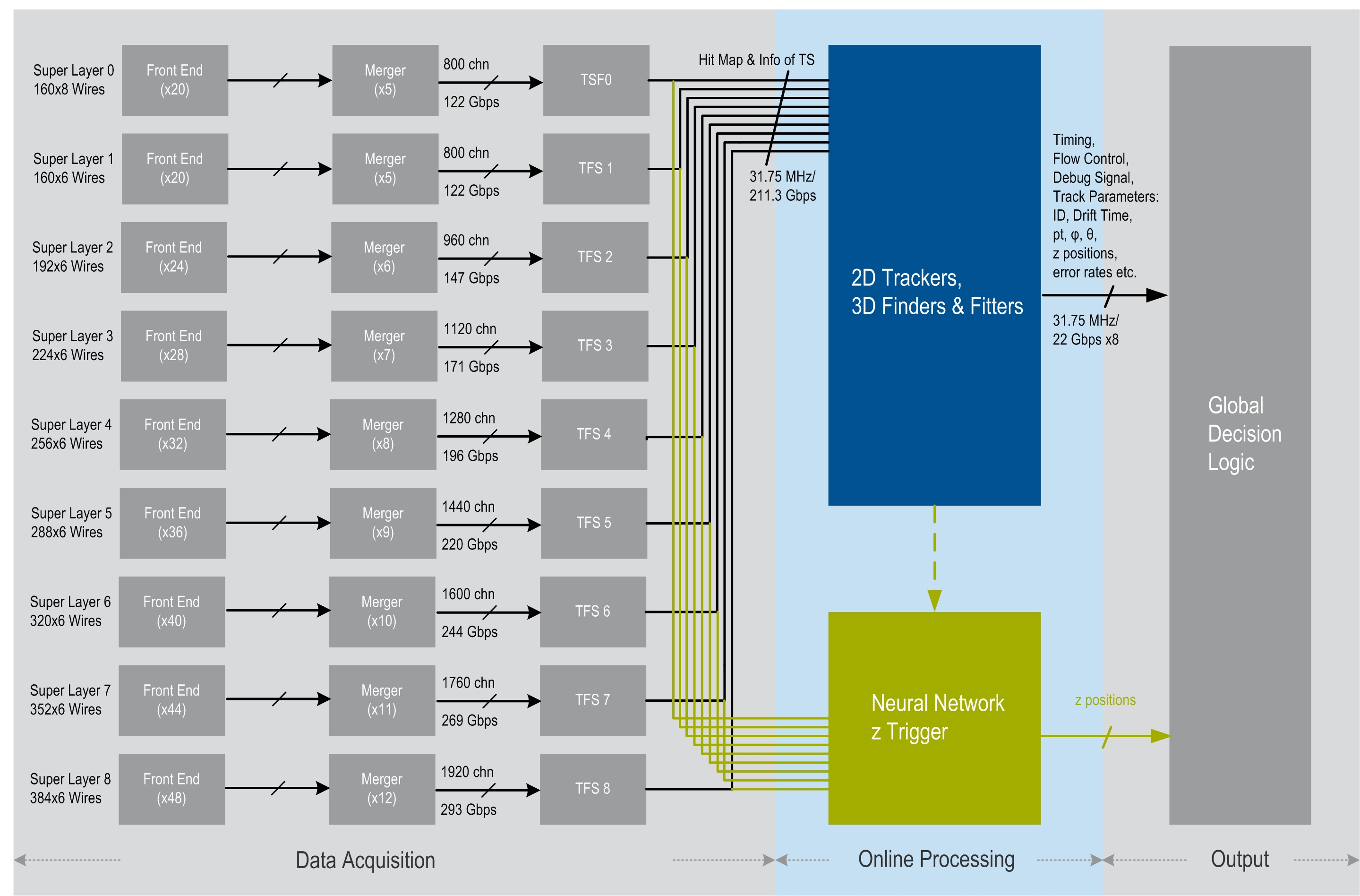
Figure 2. Schematic of the CDC trigger. Also shown is the proposed z-vertex trigger, which will run in parallel to the standard CDC track trigger.
The signals from the 9 superlayers with 14336 sense wires in total are first read out in parallel in the front-end electronics boards, where they are digitized by 10 bit 63.5 MHz ADCs (leftmost column of boxes in Fig. 2), producing a data rate coming out of the CDC of 1784 Gbps. These digital signals are then multiplexed by merger boards (second column in Fig. 2). The strategy of the present CDC track trigger is based on so-called track segments (TS), which are produced for each of the 9 superlayers as shown by the 9 sets of boxes labeled “TSFi” (third column in Fig. 2). A track segment is topologically defined by an “hour glass” shaped arrangement of 5 given layers within a superlayer with a “priority wire” in the center layer, and 2 wires in each of the adjacent layers, followed by 3 wires in each of the two layers further out (see Fig. 3).
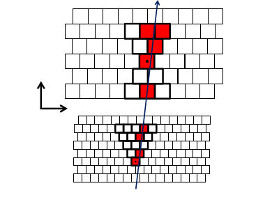
Figure 3. A track segment consisting of 5 layers in a superlayer. The priority wire is indicated by a dot. Top: one of superlayers 2-9, bottom: the innermost superlayer 1.
Within a superlayer many such track segments can be formed to cover the full azimuthal range. A total of 2336 TSs are pre-defined in the entire CDC. The track segment finder (TSF) in the CDC trigger logic combines the information in each of the hour glass regions and produces a TS if at least 4 wires in different layers have a hit. The TSF then transmits the TS number and the drift time of the priority wire for further processing (see “2D trackers” and “3D finders” in Fig. 2).
The 2D tracker follows the strategy of the previous Belle CDC trigger, combining TSs from the superlayers with axial wire orientation to provide 2D tracks in  space. The 3D finders aim at providing 3D tracks in order to determine the z-vertex of the event and to reject events not coming from the primary vertex (further details can be found in [4]). The outputs of the 2D/3D finders are finally fed into the Global Decision Logic (GDL), which combines the results of all subtriggers and makes the final decision (see right-most column of Fig. 2).